So, recently, I left Fry’s after almost 4 years. I don’t miss working at Fry’s except for 1 thing: custom builds. They were all different and all cool. I don’t think that part will go away for a while. Well, I have my own build. I have installed a few new things since the last full rebuild. Sometimes, you “shoe horn” things in that would be better with a fresh start. Today, I am giving my build a fresh start. I was able to pick up some wire ties at Fry’s. Yes, they are still open. I still fear for them because I have friends that work there and I don’t want them to be out of a job… that being said, I never want to ever have to work there again. But, I would shop there if they actually have something in stock that I am looking for…
So, I thought I would document and blog my complete rebuild. Mistakes and all. Let’s get started!
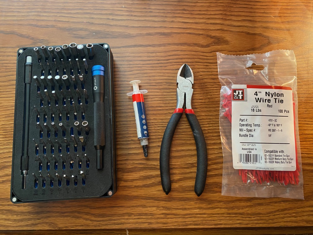
Figure 1. Tools of the trade. My iFixit tool kit, thermal paste, wire clippers/cutters, and wire ties.
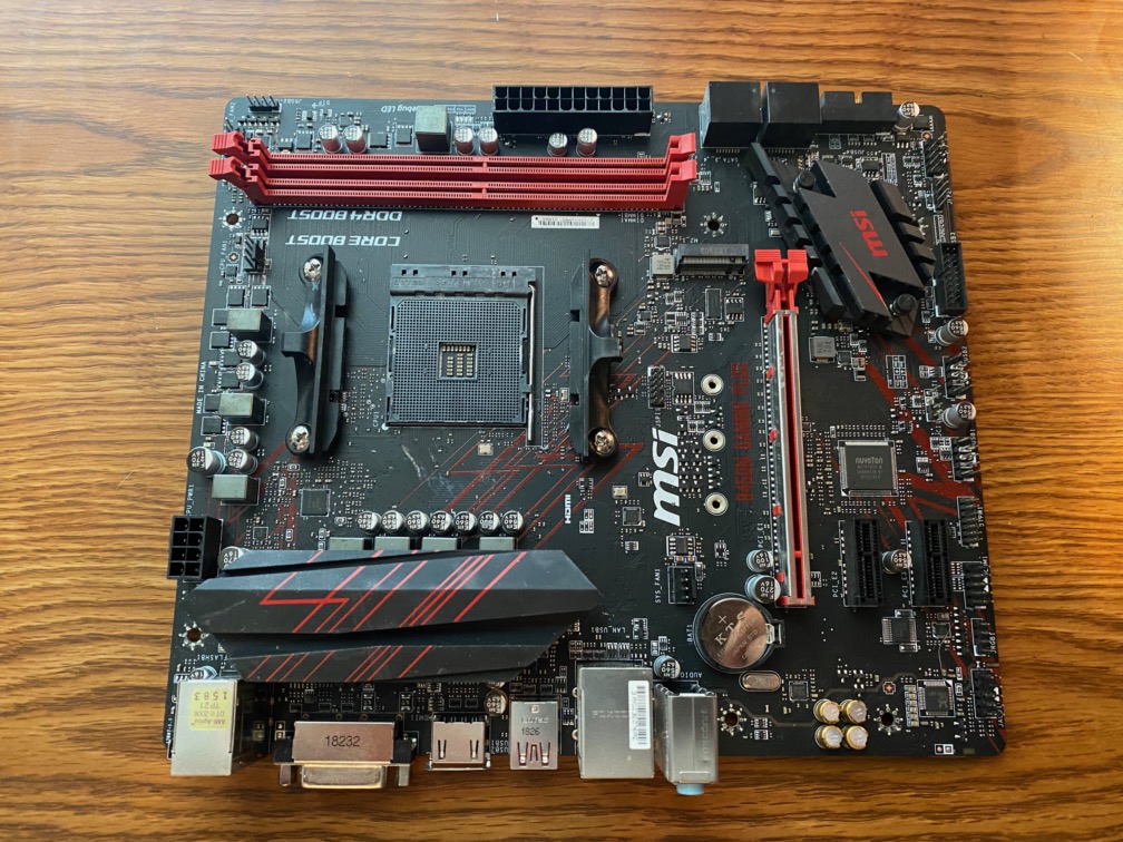
Figure 2. My bare motherboard. MSi B450M Gaming Plus. AMD AM4 Socket. This board has room for 4 DIMM slots, but only has 2. This only cause issues if I want to upgrade RAM, but I have a 16GB kit, so not likely to need more anytime soon.
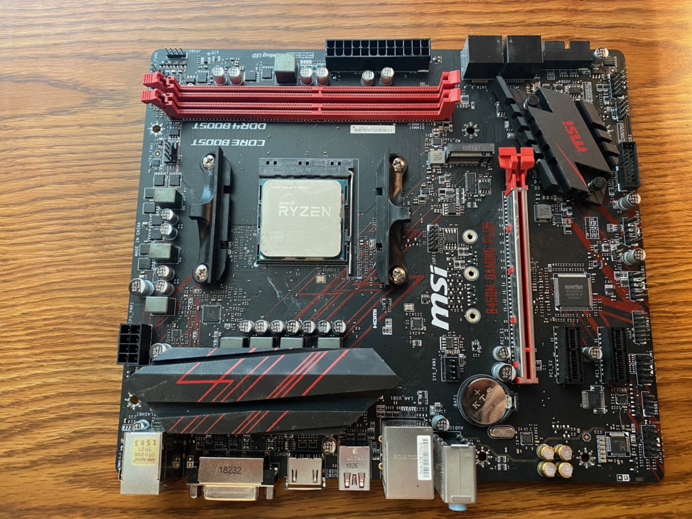
Figure 3. CPU installed. Ryzen 5 1600X.
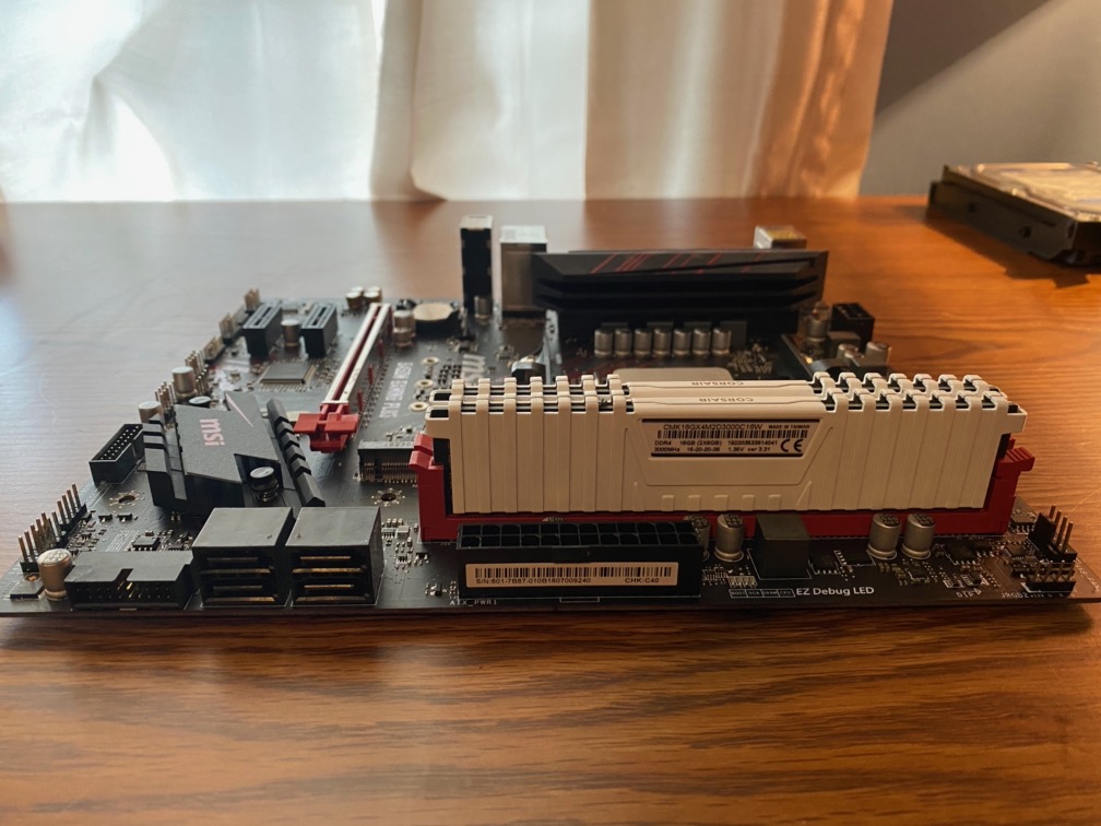
Figure 4. RAM kit installed. Corsair Vengeance LPX DDR4 3000MHz.
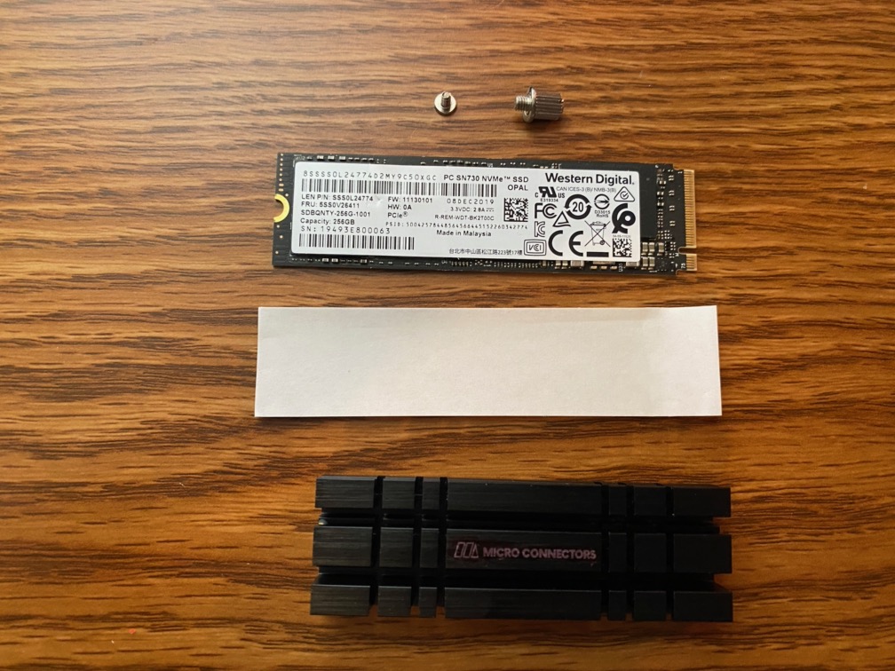
Figure 5. Preparing for SSD install. This motherboard did not come with a heatsink for the SSD. I am not sure it needs one, but I bought one. I tried to hide the brand name. It wasn’t really successful, but it’s better than it was. SSD is a Western Digital SN730 OEM part. It is a SanDisk part relabeled as a WD part. It screams, much faster then the Mushkin drive I had.
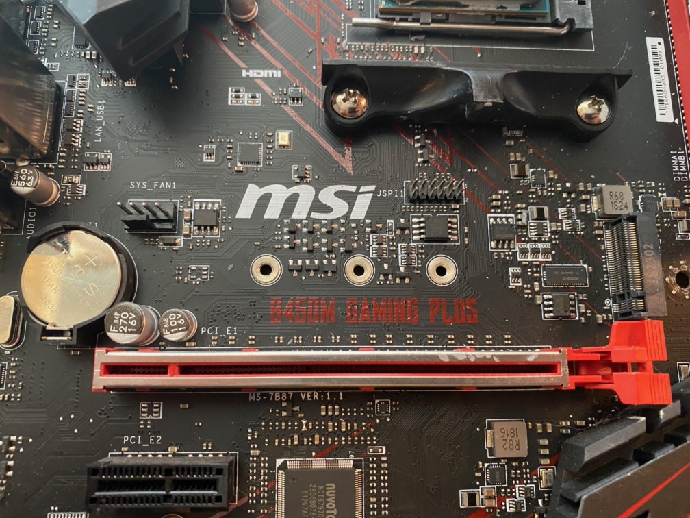
Figure 6. Looking at the board and ready to install the SSD stand-off.
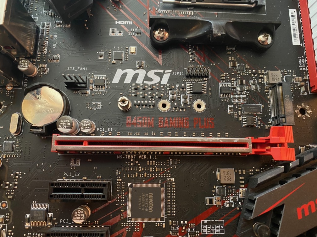
Figure 7. Unlike The Verge in their infamous build, I installed the stand off for the SSD.
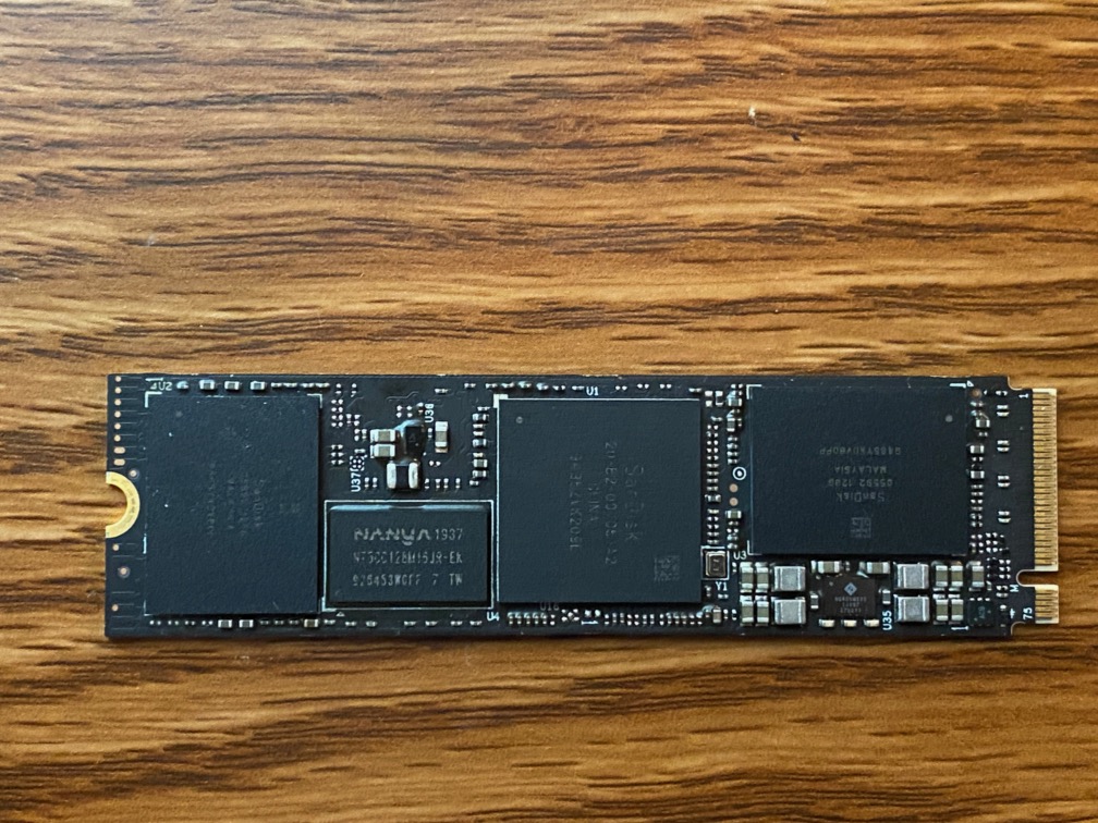
Figure 8. In preparation for the thermal pad, I had to remove the label revealing the SanDisk chips. I believe that WD bought SanDisk a few years ago…
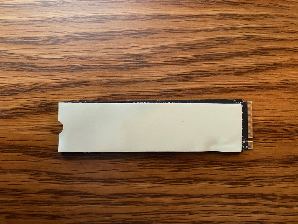
Figure 9. I probably should have reapplied the thermal pad, but it does cover the chips… But I did cut off the excess on the mounting end and made a cut out for the screw.
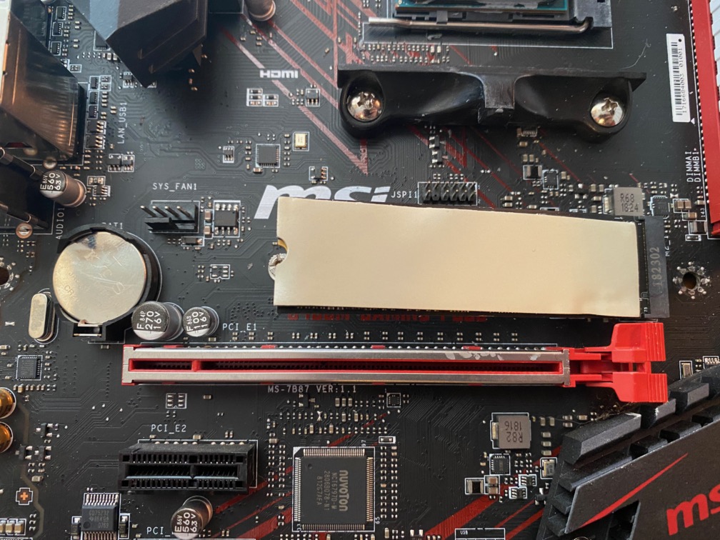
Figure 10. Installed the SSD in the connector…
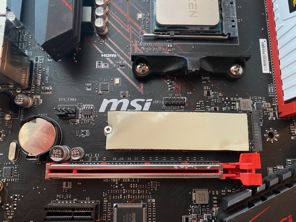
Figure 11. All screwed down and nowhere to go…
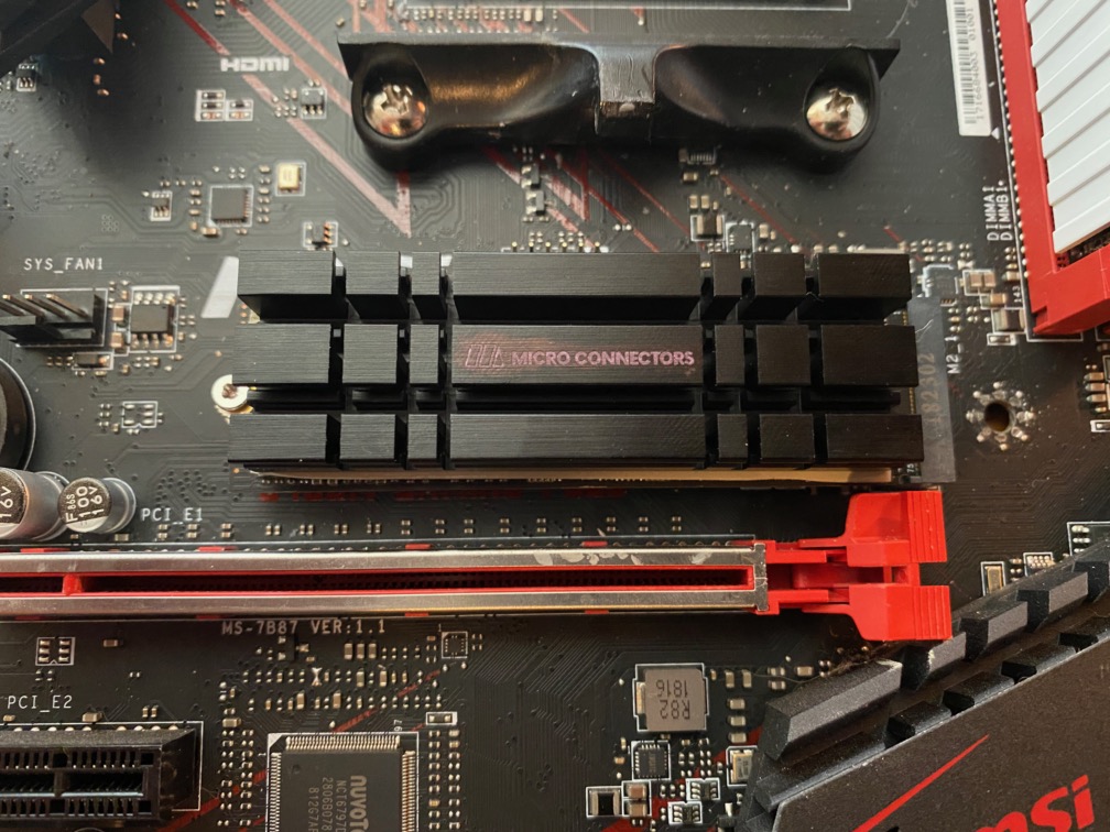
Figure 12. Installed the heatsink. There are some rubber … bands… that I was supposed to use, but I decided not to, I think it will be just fine. The part of the thermal pad that is showing will be very hard to see once the GPU is installed.

Figure 13. Haven’t installed a thing and it is already a wire mess just from the case wires… front panel (HDD light, power button, power light, USB 2.0, USB 3.0, and front panel audio)
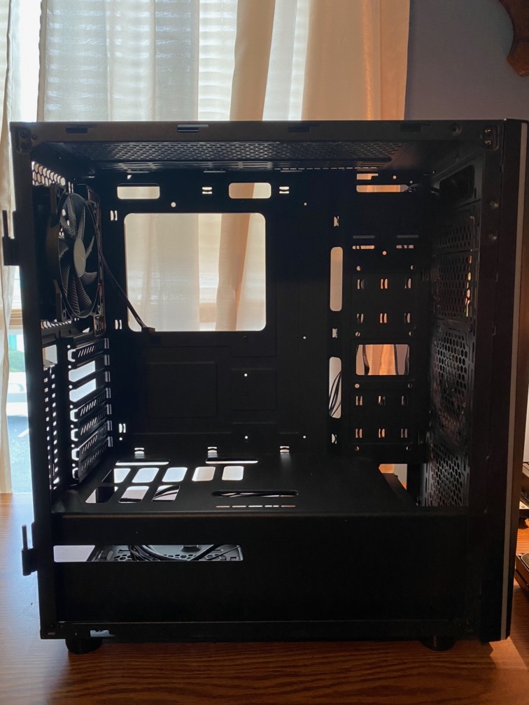
Figure 14. Looks so empty. The only part that I added to the case that I didn’t remove for the rebuild is the beQuiet PureWings fan on the rear of the case. No need to remove and screw back in….
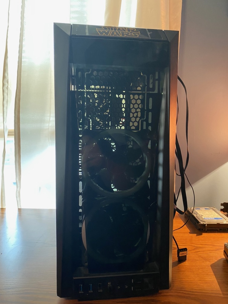
Figure 15. Front of the case and the pre-installed fans. I want to replace those with ARGB fans like my other fans…
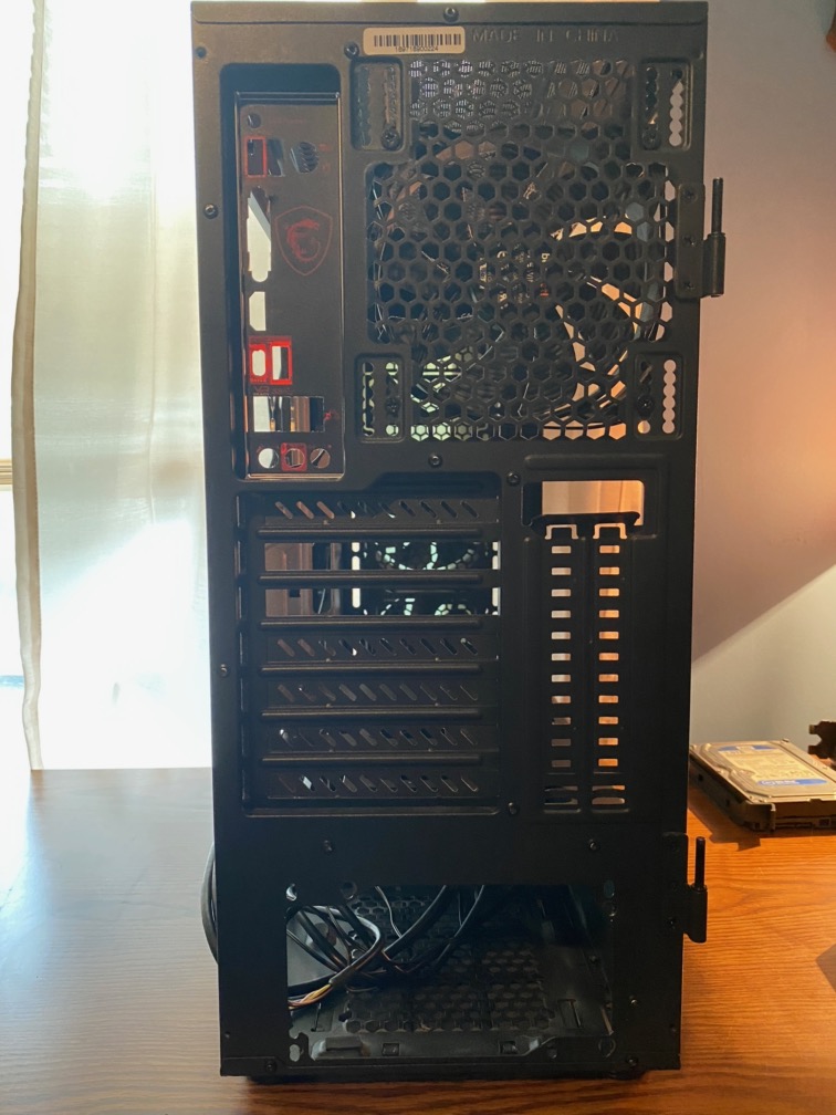
Figure 16. Rear of the case.
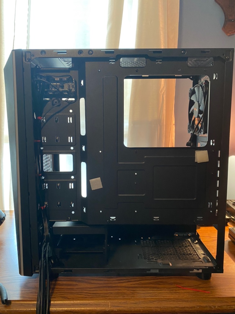
Figure 18. I went ahead and started doing a little cable management. The more I do now, the easier (ahahaha) it will be later.
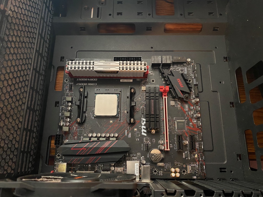
Figure 19. Motherboard installed, well laid correctly in the case. Normally, I would have done a POST-test prior to motherboard installation, but since I know my machine works, I decided to skip that step. With any new parts even in an old build, a POST test can be a time saver if any parts are bad later on. Especially, if you have a bad motherboard. It’s happened to me at Fry’s. Put it together and go to turn it on and NOTHING. Have to take it back apart and replace the motherboard. So, it really does happen to the best of us. I am hoping that all builders POST-test prior to installing in case and everything that goes on top of it.
NOTE: A POST-test is where you setup the motherboard outside of the case and connect to a monitor. Power on the motherboard and make sure it makes it to the POST screen and even into the BIOS. That is helpful so you can see if the BIOS shows the correct CPU, memory, and even storage if you have any attached. Might even do BIOS updates while it is in that configuration.
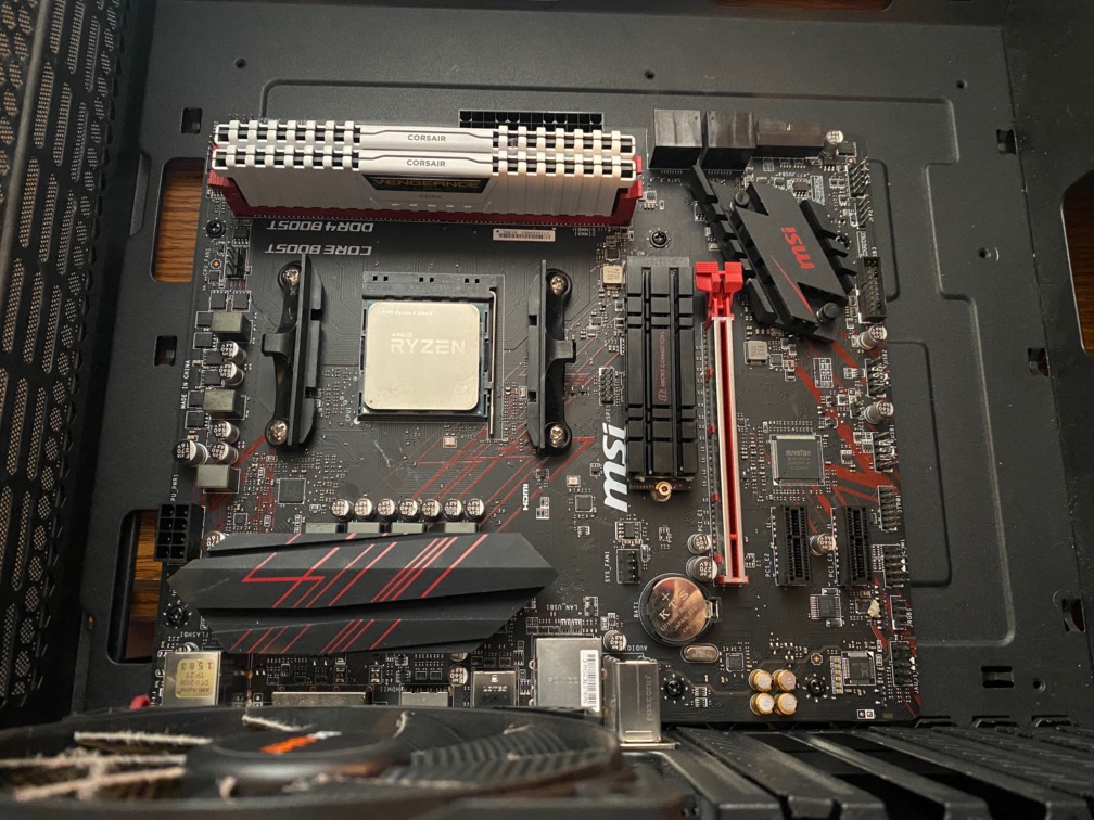
Figure 20. All motherboard screws in and tight, but not too tight. Looking good so far…
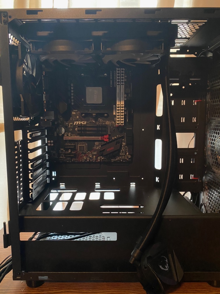
Figure 21. Installed the liquid cooler. I did leave the fans attached to the radiator in the teardown. I eventually had to move the radiator…
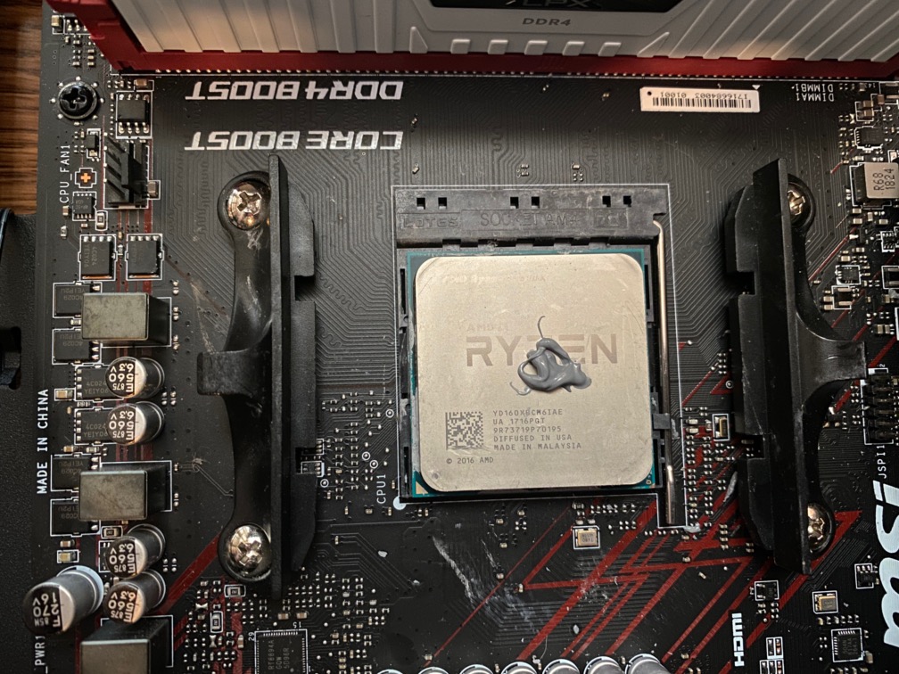
Figure 22. Lay down that thermal paste. Here some people like to do the X method, some like to manually spread it, but most people just put a dab in the middle of the IHS and let the cooler spread it out when it is installed. In this case, a CPU water block for my “All in one” liquid cooling system: MSi LiquidCool 240R. The only thing this kit didn’t come with was an ARGB controller. I bought one because my motherboard had DRBG (digital RGB) and not ARGB (Addressable RGB). These are not compatible. dRGB is like for RGB st
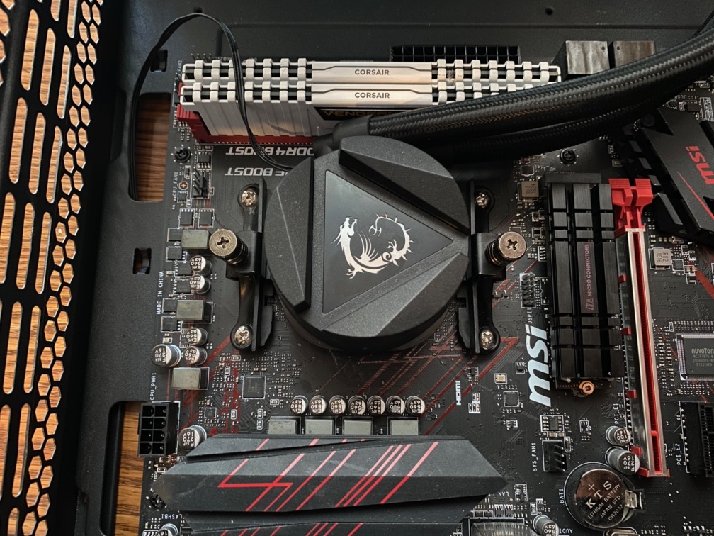
Figure 23. Moutning the water block. Most All-in-one liquid coolers integrate the pump with the water block, but MSi builds the pump in the radiator instead of the water block; however, installation should be the same.
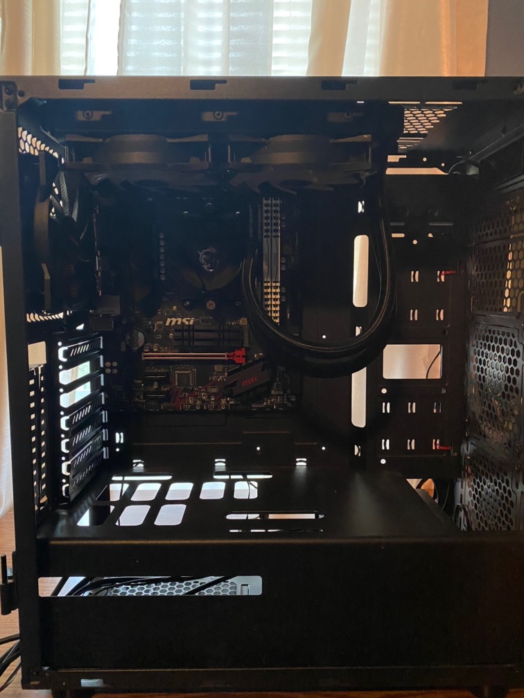
Figure 24. Installed the radiator and fans. Where it stays mounted is always fluid… (pun intended)!
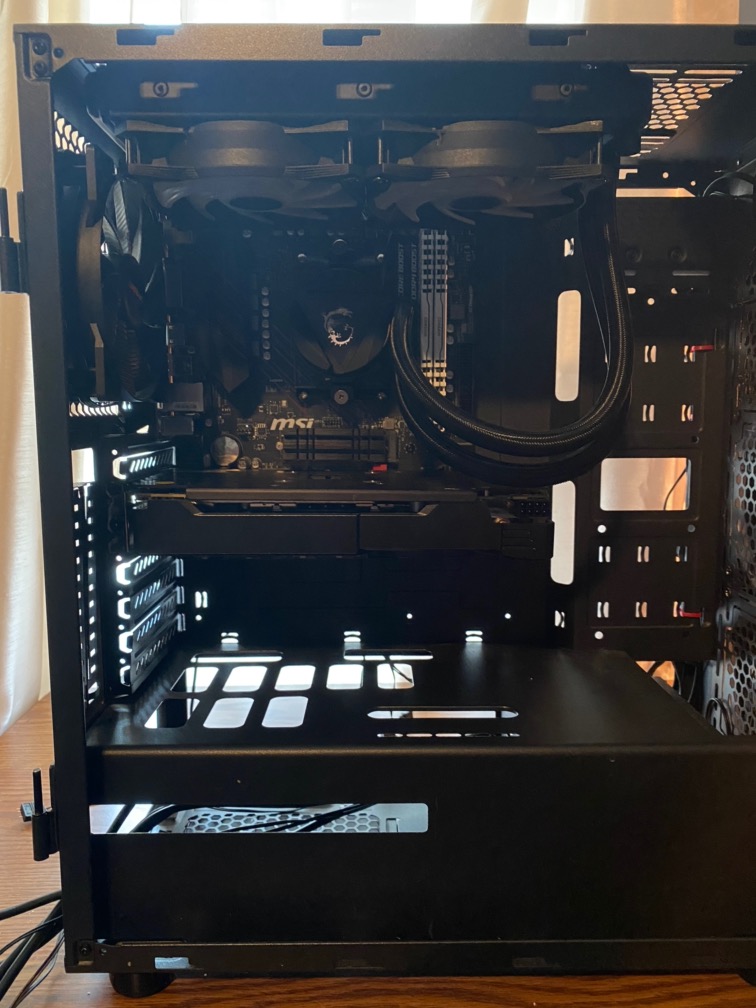
Figure 25. Installed the GPU
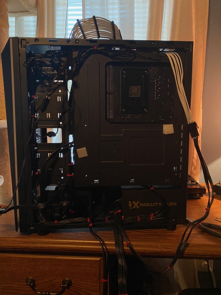
Figure 26. Look at that mess of wires.
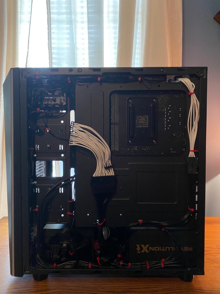
Figure 27. I tried to run the cables and tie them down and look pretty good. I am sure others could do a bit better, but this side of my case is a solid side panel, so nobody will actually see this side of the computer, anyway.
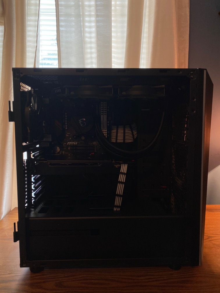
Figure 28. I moved the radiator further forward so the EPS cable can be seen. Ready to power on.
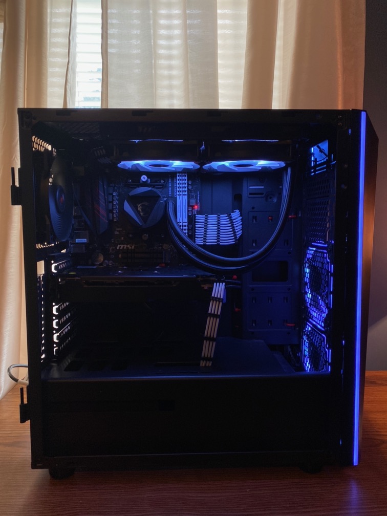
Figure 29. It turned on. Notice anything? Well, I didn’t until later and they are rookie mistakes…
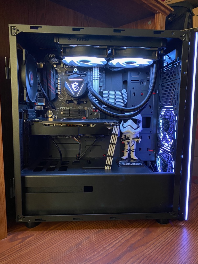
Figure 30. I figured out one of the issues… notice the one I still didn’t fix until much later… even after I had been stress testing it and something just wasn’t right.
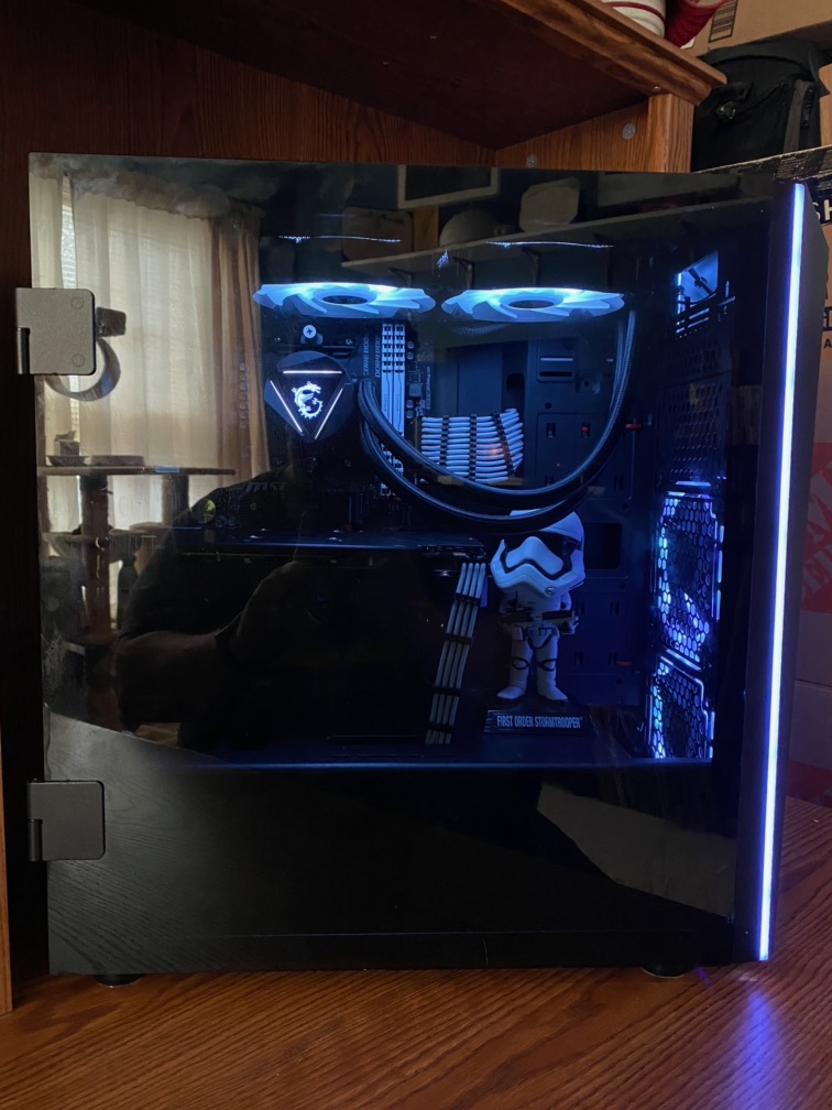
Figure 31. I put the side panel on…still haven’t noticed. Rookie mistake! Can’t believe I didn’t notice…
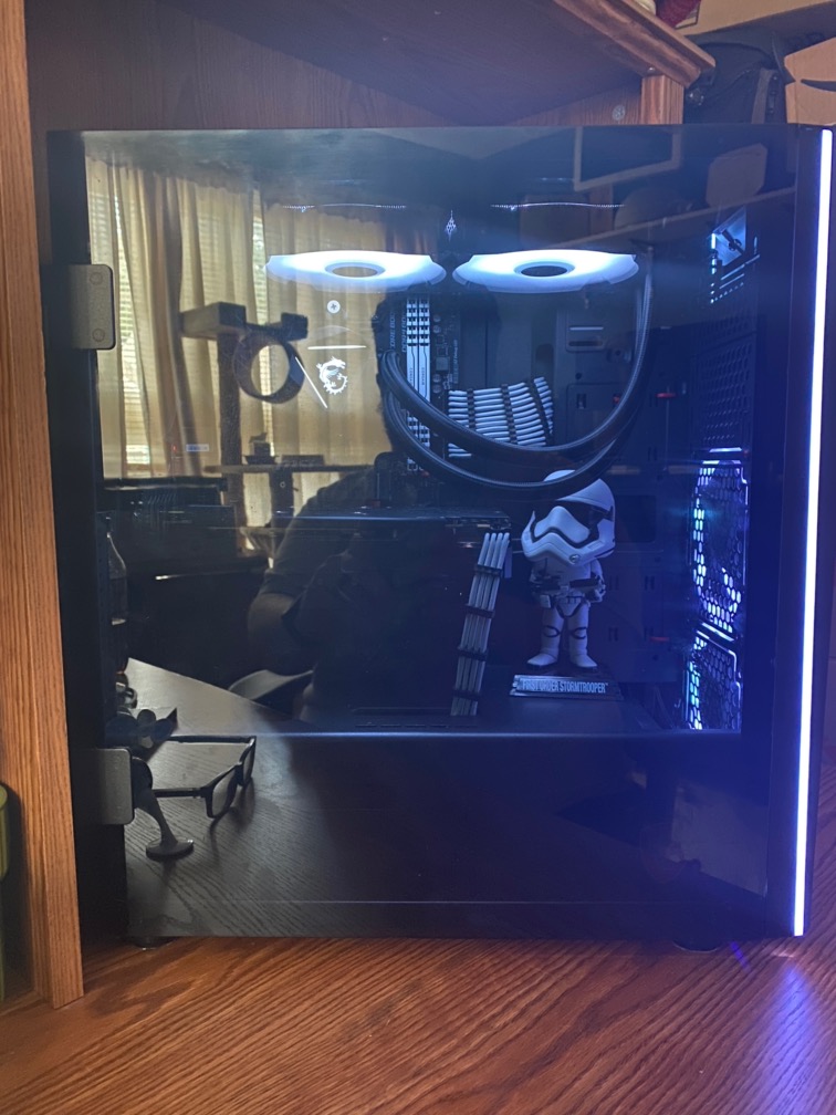
Figure 32. Looks like I figured it out.
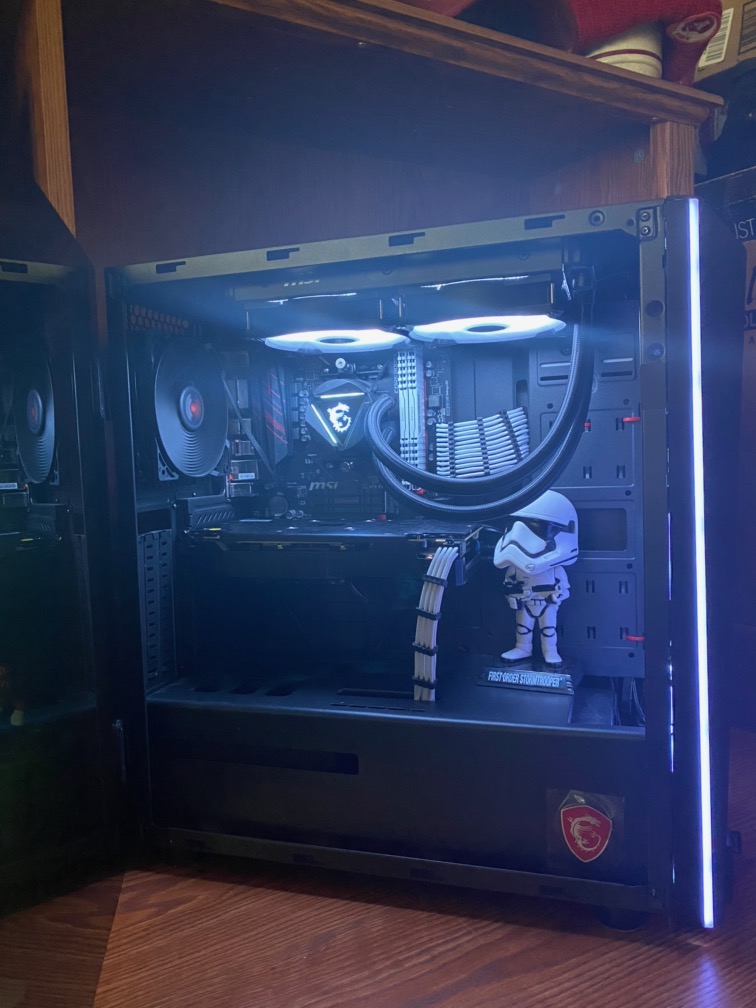
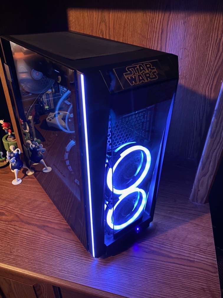
Figure 33. I had to open the door and let the lights out. Looking good!
Figure 34. I am proud of my build… I would like to upgrade a few parts at some point… but it really looks good…


